

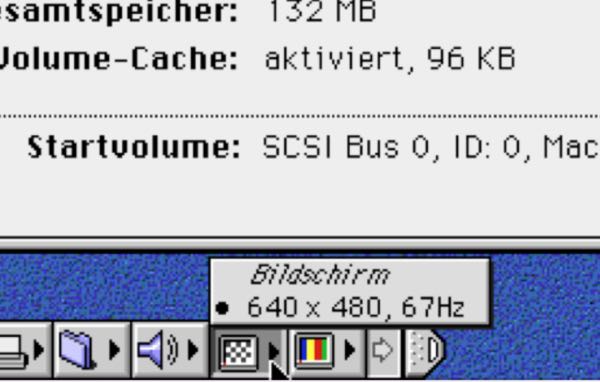
Increase the screen resolution to 640x480
The Color Classic is brought to us by Apple with a native screen resolution of 512x384 and a 60Hz refresh rate. To get the better resolution it's not very hard, but you should decide very wise because there is more than one way to get 640x480. For me it was the hardest part to get all these information together because doing a 640x480 mod is a little bit of a faith ask.
To give you a little more information and a better understanding what is happening when you do the different mods is a very useful knowledge when you want to do further steps, for example, the Takky Upgrade to the Mystic Upgrade.
In all different mods, the horizontal deflection voltage of the CRT will be changed this is achieved by changing on the analog board. One way is to change the horizontal deflection voltage to 68,4V this is ending up with a refresh rate of 60Hz in the CRT - the so-called VGA Mod. The second way is to increase the horizontal deflection voltage to 84V which ends in 67Hz refresh rate in the CRT - the so call Hi-Res or 13" Mod. Some of you will now say: "nice, lets max it out and take the 67Hz because it has not so much flicker". That's correct but increasing the horizontal deflection voltage to 84V will put more stress on the logic board. The logic board of the color classic is a very weak one out of stock and that's why it recommended putting not so much stress on it. There is one new way to get 67Hz with 640x480 which puts not so much stress on the analog board but that I will explain later. To give you a quick overview, the CCSCC(which pages are unfortunately down) has created the following table to get a better understanding what possible:
| your mod. | result | notice | ||
|---|---|---|---|---|
| hor. defl. volt. | sense line | resol. | analog board burden | |
| 60V | 12" | 512x384 | original config |
original config |
| 68.4V | 13"(HiRes) | Don´t works | light | Not recommended |
| 68.4V | VGA | 640x480 | light | Option 1 below - Recomended |
| 84V | 13"(HiRes) | 640x480 | heavy | Option 2 below - For standard analog board |
| 84V | VGA | 640x480 | heavy | Not recommended |
For more background information you have to know how the screen gets the new resolution. Changing the horizontal deflection voltage is part 1. Part 2 of every mod is to change the so-called "sense lining" which you already mentioned in the table.
In the years the color classic was introduced apple is working with sense lining to let the connected monitor know which resolutions the CRT can work with - this Part 2 of every mod: we have to tell the CRT wich resolution and refresh rate it should display. Apple is doing this by using three unused lines in the standard DB-15 VGA Connector. For all who want to learn more about sense lining, Apple is providing a good technical description which can be found here. Sense Lining is a binary code on three physical lines - you reach "0" by connecting the line to ground or "1" by leaving the line unconnected. For us, interesting are the two described sense line codes for VGA or the HiRes(13") Mode.
For VGA Mode you have to connect Sense Line 0 and Sense Line 1 to each other, while Sense Line 2 is left unconnected. For HiRes Mode you have to connect Sense Line 0 to ground and leave Sense Line 1 and 2 unconnected. I will describe them in the two options in the bottom.
The wiring of the Lines can be done in any position of the wires which are connected to the logic board because we have to let the logic board know which resolution it should display. If you are doing a Takky Upgrade I recommend to do it in the wires of the harness because you have to rewire them anyway. If you do a Mystic Upgrade or use the stock color classic logic board I recommend to do it on the analog board because you can change the logic board and keep the modification if you want to change the logic boards.
or use the stock color classic logic board I recommend to do it on the analog board because you can change the logic board and keep the modification if you want to change the logic boards.
Important: The original color classic logic board is not obtained to use 640x480 with 68,4V you have to do the HiRes Mod.
But now: lets go to do it!
Option 1: 68,4 V - VGA Mod
Step 1: Increase the Voltage
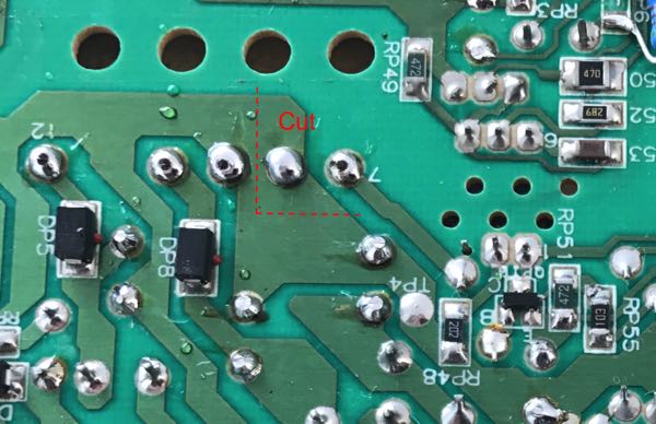
Isolate Pin 8 (left of pin 7) on the power transformer. Use a file or even better a dremel.
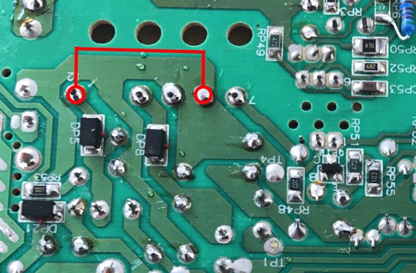
Solder a jumper from pin 8 to pin 12 - please use isolated cable. Use a standard cross-section 0,75qmm electric cable.
Step 2: New Sense Lining
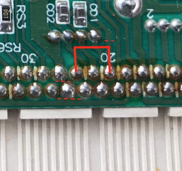
- First remove the jumper at J78
- If you don't have J78 you have to disconnect (isolate) pin 20 with the Dremel or a file.
- Disconnect (isolate) pin 25 with the Dremel or a file.
- Solder a wire jumper from pin 20 to pin 24
Option 2: 84V - HiRes Mod
Many years ago there was a first try to increase the Voltage to 84V to use the HiRes Mode. I will not describe this one because today there is a much more efficient way. The first HiRes Mode produces very high stress to the analog board. It's safer to do it in the way as techknight describes it in the forum of 68kmla.org under: "Color Classic VGA Mod. the CORRECT way". Techknight reverse engineered a never released developer version of the analog board where significant design changes have made directly from an Apple engineer. The results are that the board is more stable and can better work with the 84V HiRes Mod. You have to change much more components on the analog board but its really worth to do it.
Once Again: You have to do this mod if you wanna stay with the standard color classic logic board.
Step 1: Increase the Voltage
| Component Name | Old Value | New Value |
|---|---|---|
| CL9 | 3.3µF 160V | 2.2µF 160V |
| CL10 | 3.3µF 160V | 1.8µF 160V |
| DL21 | ? | 18V Zener BZX85C18 |
| DL22 | ? | Remove |
| RP6 | 4.52K Ω resistor | 5.11K Ω resistor |
| RP8 | 15K Ω resistor, 5W | 33K Ω resistor, 5W |
| RF14 | 236K Ω resistor | 216K Ω precision resistor 1% |
| RP23 | 22K Ω resistor, 3W | 33K Ω resistor, 3W |
| RL54 | 33 Ω resistor, 1W | 15 Ω resistor, 1W |
| RP61 | - | 7,5K 3W resistor |
| RL62 | 47 Ω resistor, 1W | 100 Ω resistor, 1W |
| RL70 | 33K Ω resistor, 1/8W | 22K Ω resistor, 1/8W |
| J104 | Jumper | 10 Ω 2W resistor |
The left standing components have to exchanged
Step 2: New Sense Lining
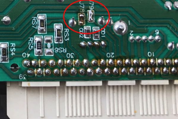
Thats really simple for the standard color classic logic board and the mystic upgrade! Just remove the Jumper J78 and close the Jumper J79. For Takky Upgrade see the note on the Takky Upgrade page.
If you are ready it looks like this :-)
Display orientation after ModWhen you are done and your screen is showing 640x480 you will be happy at first. The second thing you will see is that you have to adjust new. You have to do the most settings new because the whole screen is used now under different settings.
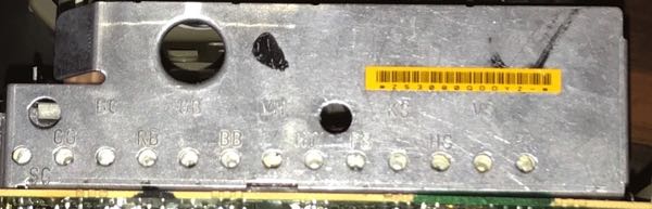
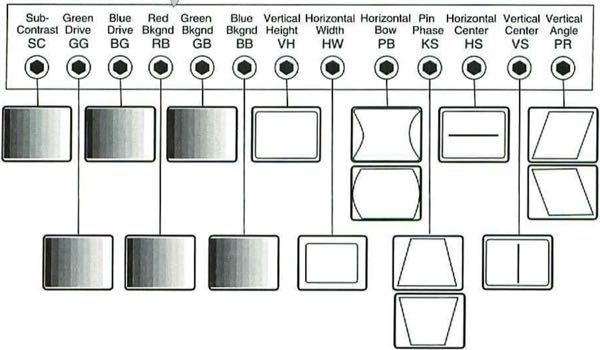
For doing the screen settings there are several potentiometers. You find them on the back and on the side of the analog board. The important ones are on the Back. The picture on the left shows you what effect the potentiometers will have.
Apple has developed an own tool the "Apple Display Service Utility" wich shows test pattern for adjusting the display settings. You find it on the downloads page.
On the downloads page you also find the original Apple Service Manual for the Color Classic. There are some more descriptions of the possible settings.
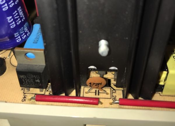
It sometimes happens that you cannot stretch so much to let the black borders disappear. That's because of the higher deflective voltage. By an idea of a long gone website of the ccscc it is possible to add a small capacitor on the empty CL26 position. The larger the capacitor the larger the effect. You can experiment with 1nF - 4nF, 1600V capacitors. In my opinion, I only see the effect starting from 3nF but it depends on your analog board.
If your black borders are very strong after the 640x480 mod and the CL26 capacitor brings not the effect you can do one more thing.
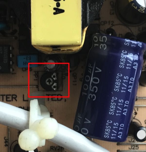
But be warned, this is a little bit risky! There is a small potentiometer on the analog board called PP1. Turning the PP1 tight raises supplying voltage. Please control raising the Voltage at the test point TP1(connected to chalk coil LP5) with a power meter and drive it slowly up to 84V.
With the words from the CCSCC:
This adjustment effects +60V (+84V, after remodeling), +24V and +8.4V. It effects to geometry adjustment and video adjustment like as horizontal drive transistor, horizontal pre-drive FET, pin phase correction IC, vertical drive IC, video processing IC and RGB gain adjustment (green gain and blue gain only at Color Classic).
Mr.Tak told if you want to adjust at any cost, please adjust carefully it with measuring the voltage by using voltage counter.