

Teardown
Before we start with hardware optimization we have to take our Color Classic apart.
Warning: The Color Classic contains a high voltage and a high-vacuum picture tube. To prevent serious personal injury or equipment damage, review CRT safety and discharge the CRT before you start work. Never use a grounding wriststrap until after discharging the CRT.
Warning: The Color Classic contains a high voltage and a high-vacuum picture tube. To prevent serious personal injury or equipment damage, review CRT safety and discharge the CRT before you start work. Never use a grounding wriststrap until after discharging the CRT.
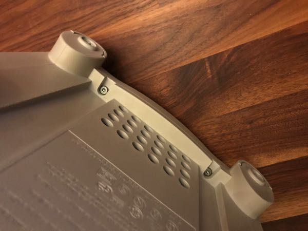
If necessary, remove the two security screws from the I/O door. Push down the two latches until the I/O door snaps open. Remove the door from the rear housing
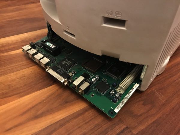
Grasp the logic board firmly with both hands and pull it straight out of the chassis. Place the logic board on a grounded workbench pad.
Grasp the logic board firmly with both hands and pull it straight out of the chassis. Place the logic board on a grounded workbench pad.
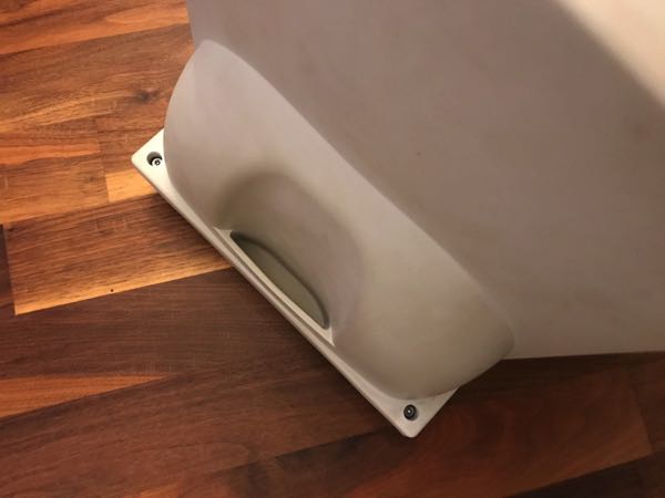
Using a long-handled Torx T15 screwdriver, remove the four case screws.
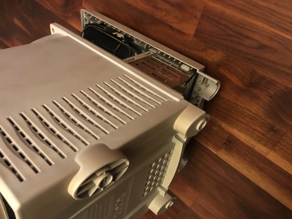
Carefully lift the rear housing and set it aside.
The edges of the metal chassis may be sharp. When moving the computer with the rear housing off, be sure to handle the chassis carefully.
The edges of the metal chassis may be sharp. When moving the computer with the rear housing off, be sure to handle the chassis carefully.
If sealant holds the video board in place, cut the sealant with an art knife.
Carefully pull the video board straight off the neck of the CRT.
Carefully pull the video board straight off the neck of the CRT.
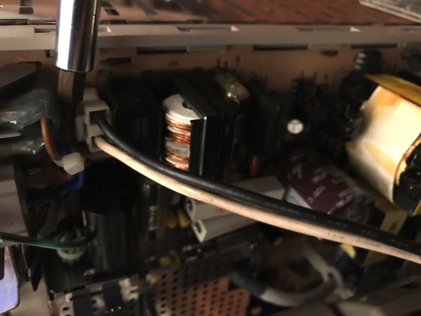
Take off the Black/White Power cable
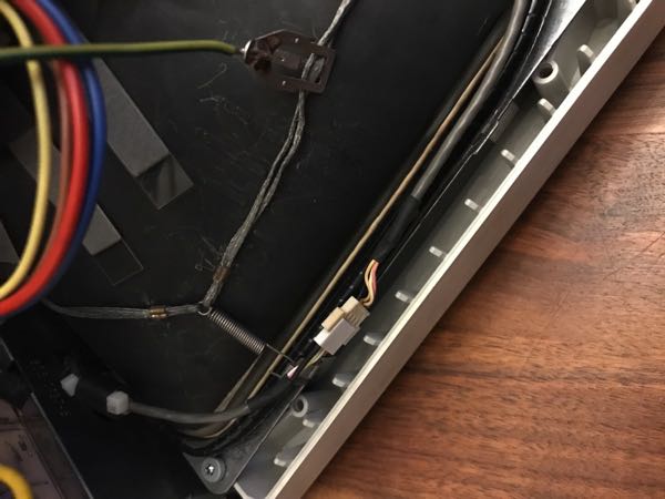
Take off the white microphone connector and unhook the video board ground wire from the CRT grounding strap.
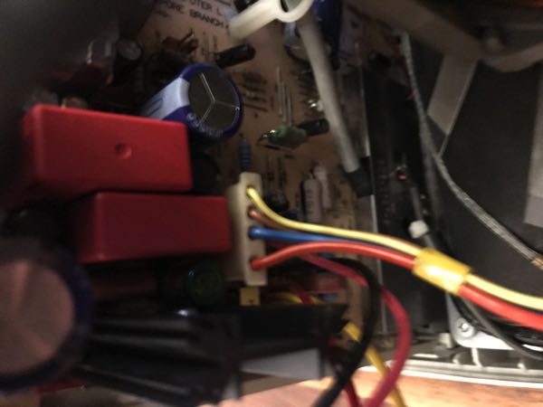
Unplug the multicolor power cable
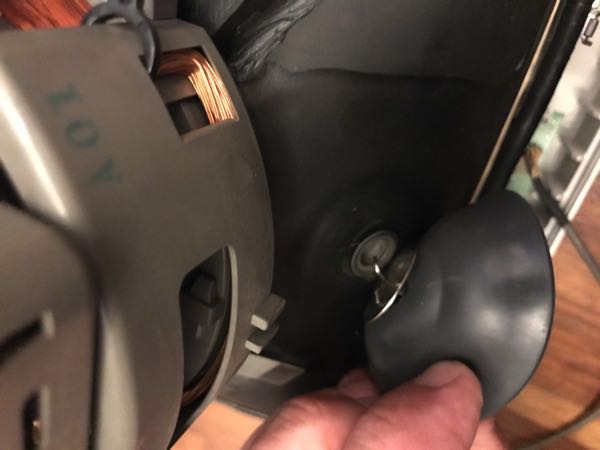
Take a flat screw driver and go under the rubber, there you can clip out the anode cap.
Remove the four self- threading screws that secure the CRT to the bezel.
Lift the CRT straight out of the bezel and place the CRT facedown on the protective workbench pad.
Remove the four self- threading screws that secure the CRT to the bezel.
Lift the CRT straight out of the bezel and place the CRT facedown on the protective workbench pad.
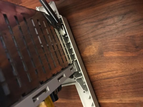
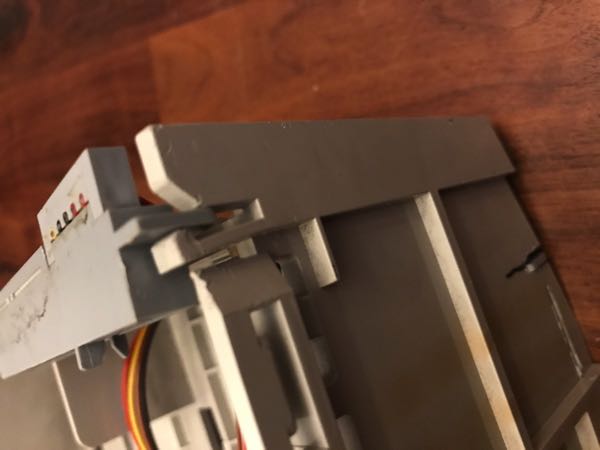
Open the two release tabs on one side of the chassis and raise that side of the chassis.
To keep the side of the chassis raised, insert a small flat-blade screwdriver between the chassis and the bezel.
Using a small flat-blade screwdriver, pry open the two release tabs on the other side of the chassis and raise the chassis.
Lift the chassis straight out of the bezel.
To keep the side of the chassis raised, insert a small flat-blade screwdriver between the chassis and the bezel.
Using a small flat-blade screwdriver, pry open the two release tabs on the other side of the chassis and raise the chassis.
Lift the chassis straight out of the bezel.
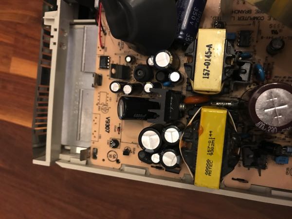
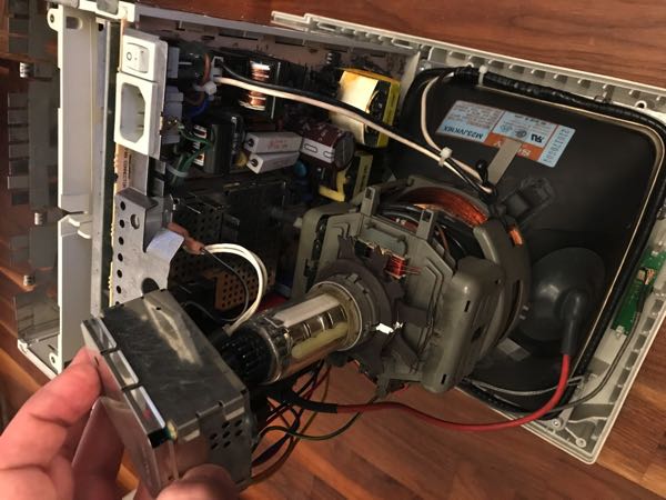
Flap back the two metal clips and then slide out the analog board. When you slide it out, remember about the cable from the speaker.
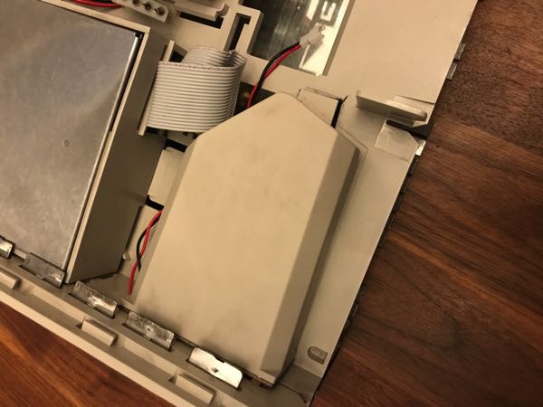
Disconnect the speaker from the Velcro
Disconnect the floppy Drive and slide the tray out - do the same to the hard drive
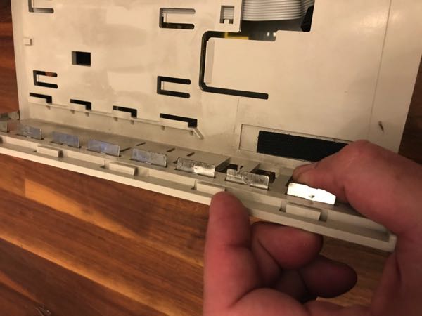
Raise and push out the mounting tabs along both sides of the bottom shield.
Remove the bottom shield from the chassis.
Set the shield aside.
Remove the bottom shield from the chassis.
Set the shield aside.
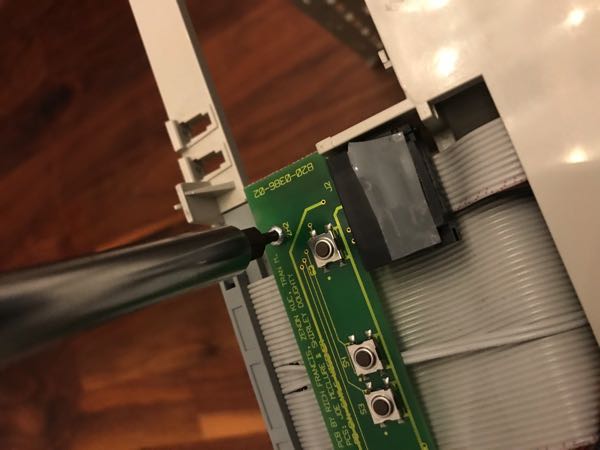
Using a T-8 Torx driver, remove the two screws that secure the pushbutton board to the chassis.
Disconnect the pushbutton board from the cable connector.
Disconnect the pushbutton board from the cable connector.
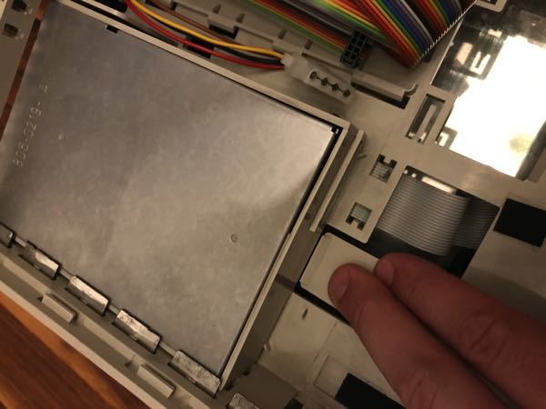
Release the plastic latch and remove the small connector bridge (to the analog board) from the chassis.
Turn over the chassis.
Push the analog board cables and small connector bridge through the access hole in the chassis.
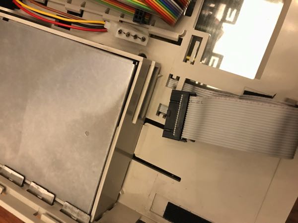
Release the three plastic latches and remove the large connector bridge (to the logic board) from the chassis.
Remove the drive cables from the plastic cable retainers, and remove the flat-cable assembly.
Turn over the chassis.
Push the analog board cables and small connector bridge through the access hole in the chassis.
Release the three plastic latches and remove the large connector bridge (to the logic board) from the chassis.
Remove the drive cables from the plastic cable retainers, and remove the flat-cable assembly.